Choosing Cone Penetrometer Equipment in 2026 is not just a price comparison. The right system must suit the ground, project scale, and available field crew. A compact push rig may fit a restricted site, while deeper investigations can require a heavier reaction system. Small details matter. Check cone capacity, data logging, calibration records, and how quickly the equipment can be serviced.
Peter K. Robertson’s published CPT work supports a practical principle: interpret cone resistance, sleeve friction, and pore pressure together rather than relying on one reading. That matters when soil layers change within a few metres. It also explains why dependable sensors and clear reporting software deserve as much attention as the rig itself. Specifications can look impressive on a screen. Field performance is the real test.
This guide compares seven options available for sale in 2026, focusing on application, measurement capability, portability, support, and overall value. It is intended as a starting point, not a substitute for checking current quotations and technical documentation. Ask suppliers about calibration, compatible cones, maintenance, and operator training before buying. A shortlist can narrow the search. It cannot predict every site condition. Some comparisons may also feel imperfect, because equipment features and local service availability vary. Confirm the details against your project requirements before making a final choice.
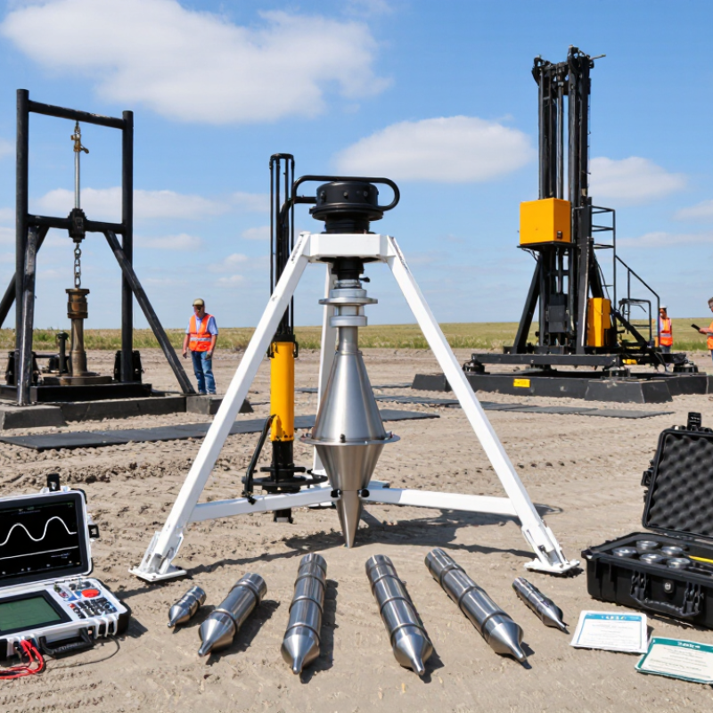
A cone penetrometer records how soil resists a steadily advancing probe. Its cone commonly has a 60-degree included angle and a projected tip area of 10 cm², though other configurations are used. The angled tip displaces soil as it moves, while sensors measure resistance along the way. Small detail matters.
The tip reading, called cone resistance, reflects the force needed to push the cone through the ground. A separate sleeve behind it measures sleeve friction: the resistance of soil sliding against that section. Together, these readings help geotechnical teams identify changes between layers, such as a firm sand seam above softer clay. The friction ratio compares sleeve friction with cone resistance, but it should not be treated as a soil label by itself.
Reliable results depend on more than the probe dimensions. Operators check calibration, keep rods aligned, and record depth alongside the measurements. A small tilt or uneven ground can complicate interpretation, and site conditions rarely behave as neatly as a diagram suggests. A plot can look precise while the ground beneath it remains variable.
| Equipment Type | Cone Geometry | Measurements or Main Components | Typical Applications | Selection Considerations |
|---|---|---|---|---|
| 1. Electric CPT system | A commonly used configuration has a 60° cone with a 10 cm² projected tip area and a 150 cm² friction sleeve. | Electronic sensors measure cone resistance (qc) and sleeve friction (fs) as the probe is pushed into the ground. | Continuous subsurface profiling and soil-behavior interpretation. | Check the data-acquisition system, depth measurement, rod compatibility, and reaction capacity required for the site. |
| 2. Piezocone CPTu system | Often uses the same 60°, 10 cm² cone and 150 cm² sleeve geometry as a standard electric CPT; pore-pressure filter location is specified separately. | Measures qc, fs, and pore-water pressure (u), commonly at the u₂ position behind the cone shoulder. | Soft clays, groundwater-sensitive investigations, and dissipation testing. | Requires a properly saturated porous filter and careful handling to obtain dependable pore-pressure readings. |
| 3. Seismic CPT system | Uses a CPT cone assembly with one or more downhole seismic sensors; the cone geometry depends on the selected CPT probe. | Combines CPT measurements with seismic wave arrival times recorded at depth intervals. | Estimating shear-wave velocity (Vs) and evaluating ground stiffness for geotechnical and seismic studies. | Confirm sensor orientation, receiver spacing, trigger equipment, and compatibility with the CPT rods and logger. |
| 4. Electrical resistivity CPT | Uses a CPT probe fitted with resistivity electrodes; electrode arrangement and spacing vary by design. | Records electrical resistivity or conductivity alongside penetration data. | Stratigraphic mapping and screening for changes in soil or groundwater conditions. | Resistivity is an indirect measurement; it does not by itself identify a specific contaminant or replace sampling. |
| 5. Mechanical cone penetrometer | A mechanical cone commonly uses a 60° tip; tip area and sleeve arrangement depend on the system and test method. | Uses mechanical rods and a reading mechanism to determine penetration resistance; electronic CPT channels are not inherent to this setup. | Investigations where a mechanical procedure is specified or electronic data acquisition is not required. | Check the method’s measurement procedure, rod system, and required reaction equipment before comparing results with electric CPT data. |
| 6. Track-mounted CPT rig | Rig platform; the CPT probe is selected separately and may use standard 60° cone geometry. | Tracked carrier, hydraulic push system, rod handling, and data-acquisition equipment. | Sites with restricted access or ground conditions where a tracked platform is useful. | Compare transport dimensions, ground pressure, setup requirements, and available push capacity for the planned investigation. |
| 7. Truck-mounted CPT rig | Vehicle-mounted rig; cone size and sensor package are selected to suit the project and test specification. | Truck carrier, hydraulic push frame, reaction mass, rods, and CPT data system. | Projects with vehicle access and a need for an integrated, mobile CPT platform. | Check access routes, overhead clearance, vehicle weight limits, reaction requirements, and local transport restrictions. |
It records resistance as a probe moves steadily into soil. The cone measures tip resistance, while a sleeve measures friction behind it.
Its angled tip displaces soil during penetration. A 60-degree included angle is common, though other configurations are used.
A 15 cm² cone needs 50% more tip force at the same resistance. At 10 MPa, that is 15 kN versus 10 kN.
No. Rod friction, depth, anchoring, and changing soil layers also affect thrust demand. Small details matter.
It measures soil resistance sliding along the sleeve. Together with cone resistance, it can help reveal changes between layers.
No. It compares sleeve friction with cone resistance, but it should not be treated as a soil label. Not alone.
Check calibration, keep rods aligned, and record depth with each measurement. Uneven ground or a tilted probe can complicate interpretation.
Compare expected resistance with usable field thrust, stroke length, and reaction capacity. A rig suited to soft clay may stall in dense sand.
No. Ratings cannot predict every soil profile. A precise-looking plot can still hide variable ground, so local data deserves another look.
This guide explains how Cone Penetrometer Equipment measures soil resistance using a standard 60-degree cone, a 10 cm² tip, and a friction sleeve. It outlines the role of ASTM D5778 and the typical 20 mm/s penetration rate, helping readers understand how consistent procedures support meaningful site data. The article also compares seven types of CPT systems by thrust capacity, achievable depth, and data-logging features.
Choosing a system depends on more than headline specifications. Cone area, expected ground conditions, and rig capacity all affect performance and suitability. Before purchasing, check calibration records, sensor options, access requirements for the site, and the availability of technical support. These considerations can help match equipment to project needs, improve the reliability of measurements, and avoid selecting a system that is difficult to operate or maintain.

 Zealchon Electronic