Choosing the best Eight Wheel Toughness Tester requires more than comparing prices or wheel counts. The instrument must match the material, test method, and production risk. Paper, coated board, and flexible packaging can react differently under repeated bending, compression, and twisting. A tester that performs well on a laboratory sample may behave differently on a dusty factory floor.
Industry demand makes this decision more important. The FAO’s Global Forest Products Facts and Figures report records annual global paper and paperboard production above 400 million tonnes. Smithers’ packaging forecasts also highlight lightweighting, recycled fibers, and stricter quality expectations. These changes can reduce material margins. Small weaknesses may appear around folds, seams, or printed surfaces. The Eight Wheel Toughness Tester should therefore provide stable wheel pressure, repeatable rotation, clear specimen alignment, and traceable calibration records.
Lord Kelvin, a pioneer in measurement science, stated, “When you can measure what you are speaking about, you know something about it.” His principle still fits modern toughness testing. However, one number never tells the whole story. A higher toughness value does not automatically mean better packaging performance. Operators should compare results with relevant ISO or ASTM procedures, conditioning temperature, sample direction, and wheel contact settings. These details matter.
Look closely at the test path. Is the specimen flat? Does the wheel slip? Is the reading steady after ten cycles? These practical observations reveal equipment quality. Supplier training, service response, software records, and replacement-wheel availability also deserve attention. The perfect tester may not exist. The right choice is the most transparent, repeatable, and defensible one for your actual materials.
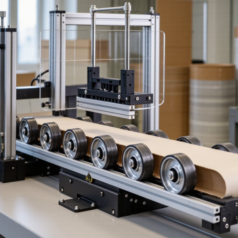
Choosing the best eight-wheel toughness tester starts with the material, not the machine. The test measures three practical signals: applied load, repeated cycles, and failure. Load shows how much force each wheel transfers. Cycles reveal fatigue under repeated rolling. Failure may appear as cracking, tearing, delamination, or permanent deformation.
Use a calibrated load cell and record force throughout the test. ASTM D4060 abrasion practice shows why load and wheel condition must be controlled: small changes can strongly affect mass loss. For flexible materials, define the cycle speed, wheel hardness, contact width, and temperature before testing. Textile Exchange’s Materials Market Report 2024 estimates global fiber production reached about 124 million tonnes in 2023. That scale makes repeatable durability data increasingly important.
A useful tester should stop automatically when the surface fails. Set a visible failure rule, such as a continuous crack or exposed substrate. Record the exact cycle count, not only “passed” or “failed.” ISO 17025 principles support traceability, calibration, and documented uncertainty in laboratory results. Test at least three specimens, because one perfect sample can mislead. I have seen operators trust the average too quickly. That is a weakness. Check wheel alignment after every run, and photograph the damage under consistent lighting. Cycles matter. Load matters more when contact changes.
The table below summarizes the main measurement dimensions used when evaluating an eight-wheel toughness tester. Example values are provided for a coherent test record and are not universal acceptance limits; the applicable product specification or test method should define the final settings.
| Measurement Dimension | Unit | Example Value | What It Measures | Selection or Reporting Guidance |
|---|---|---|---|---|
| Number of Wheels | wheels | 8 | The number of wheels distributing the applied force across the test specimen. | Confirm that the instrument uses eight independently supported or mechanically linked wheels, according to the required test procedure. |
| Applied Load per Wheel | N | 50 N | The nominal force transferred through each wheel to the specimen. | The load should be adjustable, stable, and traceable to a calibrated force-measuring device. |
| Nominal Total Wheel Load | N | 400 N | The combined nominal load calculated as eight wheels × 50 N per wheel. | This calculation assumes equal load sharing. Actual contact forces may differ if wheel alignment, stiffness, or specimen thickness varies. |
| Load Accuracy Target | % of reading | ±1% | The permitted difference between the indicated load and the verified applied load. | Use the accuracy and calibration requirements specified by the applicable method. Do not treat ±1% as a universal pass criterion. |
| Loading Mode | mode | Constant normal load | Whether the specimen experiences a controlled, repeated force during wheel movement. | Choose a tester that can maintain the required load without excessive fluctuation during acceleration, steady motion, and reversal. |
| Test Cycles | cycles | 10,000 | The number of completed loading or rolling repetitions applied to the specimen. | The tester should provide a programmable cycle counter and retain the cycle count at the moment of failure. |
| Cycle Rate | cycles/min | 60 | The speed at which repeated loading cycles are completed. | At 60 cycles/min, 10,000 cycles require approximately 166.7 minutes, excluding setup and interruptions. |
| Test Duration | min | 166.7 | The calculated exposure time for 10,000 cycles at 60 cycles/min. | Record actual elapsed time separately when the machine pauses, changes speed, or stops for inspection. |
| Wheel Contact Width | mm | 20 mm | The nominal width of the wheel footprint contacting the specimen. | Contact width affects local stress and deformation. Report the wheel geometry and verify that all wheels make consistent contact. |
| Wheel Travel Distance | mm/cycle | 100 mm | The programmed reciprocating or rolling distance covered during one complete cycle. | Use a calibrated travel system so that the specimen receives the intended mechanical displacement. |
| Test Temperature | °C | 23 °C | The temperature of the specimen and test environment during loading. | Temperature can change stiffness, friction, and failure behavior. Record the actual stabilized temperature, not only the chamber setting. |
| Peak Displacement | mm | 3.6 mm | The greatest measured vertical or horizontal movement of the specimen during the test. | A displacement sensor should have a suitable range, resolution, and sampling rate for the expected deformation. |
| Residual Deformation | mm | 1.8 mm | The permanent deformation remaining after the applied load is removed or the test is completed. | Define the measurement time after unloading because viscoelastic materials may continue to recover. |
| Failure Cycle | cycle | 8,420 | The cycle at which the specimen first meets the predefined failure condition. | Failure criteria may include a through-crack, delamination, rupture, loss of continuity, or a specified deformation limit. |
| Failure Mode | classification | Surface crack with progressive separation | The physical mechanism or visible condition that ends the test. | Use photographs, visual inspection, and dimensional measurements to support the failure classification. |
| Failure Deformation Limit | mm | 2.0 mm | An example predefined limit used to determine whether deformation constitutes failure. | The limit must come from the applicable specification or test plan; it should not be selected solely from instrument capability. |
| Data Acquisition | recorded outputs | Load, cycles, displacement, temperature, failure time | The synchronized data needed to relate mechanical loading to specimen damage. | Prefer systems that export raw data with timestamps and preserve the cycle count, calibration status, and test settings. |
| Repeatability Check | replicates | Minimum 3 specimens | The consistency of failure cycles and deformation results among specimens tested under identical conditions. | Use replicate specimens and report the mean, standard deviation, and individual failure values rather than only one result. |
| Result to Report | summary | 8,420 cycles to failure | A concise toughness result linking the applied load and test conditions to the observed failure. | Report load per wheel, total nominal load, cycle rate, temperature, specimen dimensions, failure definition, and failure cycle together. |
Important: A higher load capacity or cycle count does not automatically make a tester better. The most suitable instrument is the one that can control the required load, wheel contact, motion, environment, and failure detection with verified calibration and repeatable results.
It measures applied load, rolling cycles, and material failure. Load shows the force transferred through each wheel. Cycles reveal fatigue during repeated contact. Failure may include cracks, tearing, delamination, or permanent deformation.
Small load changes can alter abrasion and damage results. Use a calibrated load cell and record force continuously. Contact width and wheel condition also matter. Load matters more when contact changes.
Set a clear failure rule before testing. The rule might be a continuous crack or exposed substrate. The machine should stop at that point. Record the exact cycle count, not only “passed” or “failed.”
Test at least three specimens for an initial comparison. Ten identical specimens provide stronger repeatability evidence. One perfect sample can mislead. I have trusted averages too quickly before.
Check load, wheel speed, travel distance, and wheel alignment. Use traceable reference equipment where possible. Record calibration dates and measurement uncertainty. A readable number can still be wrong.
Preserve raw values, timestamps, specimen codes, and wheel condition. Include calibration status and operator details. Export files should retain audit trails. Missing fields and unusual drift need visible warnings.
Look for guarded moving parts and emergency stops. Door interlocks and overload protection add protection. Clear status indicators help operators react quickly. Loading should not require reaching near moving wheels.
Use programmable sequences and quick data export. Accessible fixtures can reduce setup time. Removable guards may simplify maintenance. Faster testing is not always better. Heat and vibration can reduce confidence. A short trial with typical wheels may reveal hidden delays.
Choosing the right Eight Wheel Toughness Tester requires more than comparing basic specifications. First, understand what the instrument measures, including applied load, wheel cycles, wear or surface damage, and the point at which a specimen fails. The selected test method should match the material and application, with attention to compatibility between ASTM D4060, ISO 5470-1, and any internal laboratory procedures. Wheel load, rotation speed, and test duration—such as a 1,000-cycle evaluation—must be selected consistently so results are meaningful and comparable.
Reliable testing also depends on verification and practical usability. Look for straightforward calibration procedures, stable repeatability, and data-logging functions that record key test conditions and results. Beyond measurement performance, compare specimen capacity, guarding and emergency-stop features, routine maintenance needs, operating efficiency, and overall test throughput. A well-selected tester should deliver dependable data while supporting safe, efficient, and repeatable laboratory workflows.

 Zealchon Electronic